

- Posts: 6326
- Thank you received: 309
Dome Automation
- michaeloconnell
- Topic Author
- Offline
- Administrator
-

Less
More
11 years 6 months ago - 11 years 6 months ago #95329
by michaeloconnell
Dome Automation was created by michaeloconnell
Below are photos of where I am as of the last few days:
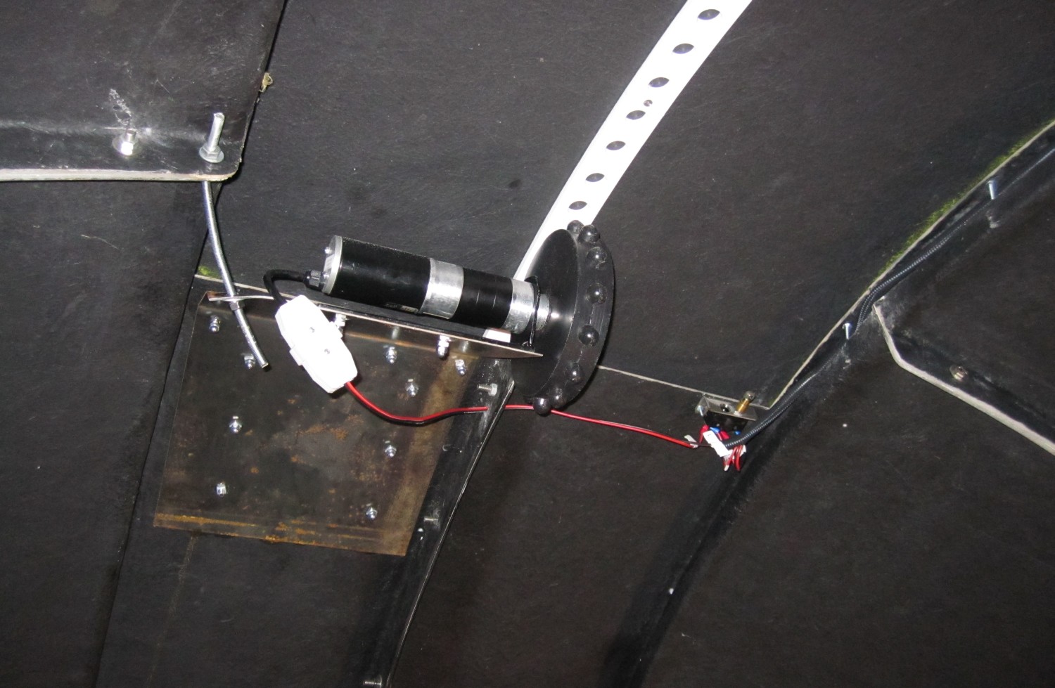
Motor for opening/closing the upper shutter. Also shows the relay which cuts the power to the upper shutter motor and transfers it to the lower shutter motor.
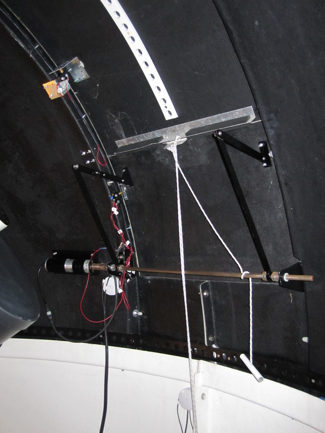
Lower shutter motor and relays. At the top of the pic is the upper shutter close relay.
Below that is the lower shutter close relay.
Below that again is the lower shutter open relay - attached to the bracket holding the motor/pivot arm.
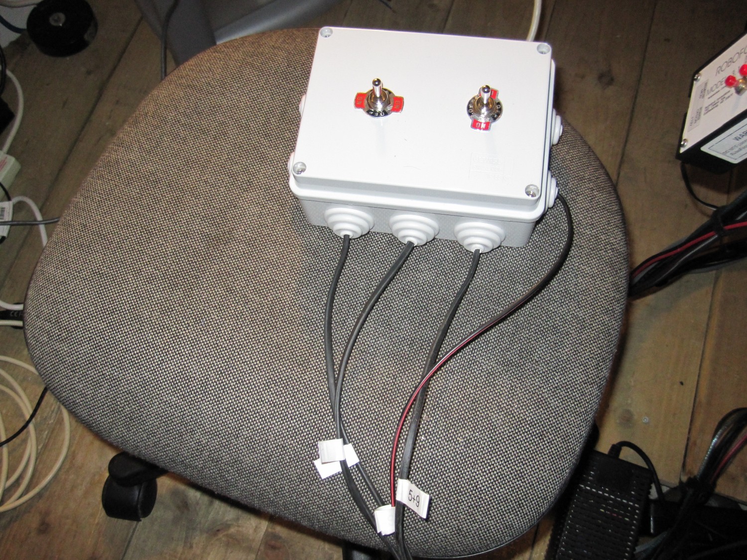
Control box at the pier.
On the RHS is the up/down momentary switch for opening closing the shutters.
On the LHS is the side-to-side monentary switch for the azimuuth motor.
Wiring of what I have done to date.
www.astroshot.com/Observatory//2012-10-10/Wiring-2012-10-10.pdf
This is where I want to get to:
www.astroshot.com/Observatory/WO-Deadman-V09.pdf
Bit to go yet I'm afraid.....if anyone is in a position to assist in translating the above wiring schematic to an actual clear diagram that I can wire things up together, it would be VERY much appreciated!
Motor for opening/closing the upper shutter. Also shows the relay which cuts the power to the upper shutter motor and transfers it to the lower shutter motor.
Lower shutter motor and relays. At the top of the pic is the upper shutter close relay.
Below that is the lower shutter close relay.
Below that again is the lower shutter open relay - attached to the bracket holding the motor/pivot arm.
Control box at the pier.
On the RHS is the up/down momentary switch for opening closing the shutters.
On the LHS is the side-to-side monentary switch for the azimuuth motor.
Wiring of what I have done to date.
www.astroshot.com/Observatory//2012-10-10/Wiring-2012-10-10.pdf
This is where I want to get to:
www.astroshot.com/Observatory/WO-Deadman-V09.pdf
Bit to go yet I'm afraid.....if anyone is in a position to assist in translating the above wiring schematic to an actual clear diagram that I can wire things up together, it would be VERY much appreciated!
Last edit: 11 years 6 months ago by darragh.
Please Log in or Create an account to join the conversation.
- albertw
- Offline
- IFAS Secretary
-

Less
More
- Posts: 4173
- Thank you received: 181
11 years 6 months ago #95336
by albertw
Are the components in the green boxes meant to be separate physical boxes or is it just a logical separation. I'm having trouble relating this diagram to the previous diagram showing what you have done so far.
What's P8055?
How is the Azimuth sensor supposed to work? It has to Photomicrosensors in it so I'm guessing that this is attached to something that will move into 'dock' with some other part of the dome and block the sensors?
The coils seem not to be just inductors, but the coils of the relays, which makes more sense! In your other diagram you appear to indicate the relays are located somewhere in isolation so they do not go on the circutboard for the 'shutter control'.
Hopefully I can help and not just add to the confusion!
Albert White MSc FRAS
Chairperson, International Dark Sky Association - Irish Section
www.darksky.ie/
Replied by albertw on topic Re: Dome Automation
michaeloconnell wrote: This is where I want to get to:
www.astroshot.com/Observatory/WO-Deadman-V09.pdf
Bit to go yet I'm afraid.....if anyone is in a position to assist in translating the above wiring schematic to an actual clear diagram that I can wire things up together, it would be VERY much appreciated!
Are the components in the green boxes meant to be separate physical boxes or is it just a logical separation. I'm having trouble relating this diagram to the previous diagram showing what you have done so far.
What's P8055?
How is the Azimuth sensor supposed to work? It has to Photomicrosensors in it so I'm guessing that this is attached to something that will move into 'dock' with some other part of the dome and block the sensors?
The coils seem not to be just inductors, but the coils of the relays, which makes more sense! In your other diagram you appear to indicate the relays are located somewhere in isolation so they do not go on the circutboard for the 'shutter control'.
Hopefully I can help and not just add to the confusion!
Albert White MSc FRAS
Chairperson, International Dark Sky Association - Irish Section
www.darksky.ie/
Please Log in or Create an account to join the conversation.
- martinus
- Offline
- Main Sequence
-

Less
More
- Posts: 274
- Thank you received: 104
11 years 6 months ago - 11 years 6 months ago #95340
by martinus
Replied by martinus on topic Re: Dome Automation
I suspect that the P8055 is a USB interface board:
www.velleman.eu/downloads/0/illustrated/...al_k8055_uk_rev3.pdf
I suspect that you're correct albertw - the 'coils' are all denoted Kn where n is a relay coil
The circuit would be much clearer were standard symbols used for the relays:
en.wikipedia.org/wiki/File:Relay_symbols.svg
Interestingly, mouser considers the relay model to be obsolete.
www.mouser.com/ProductDetail/TE-Connecti...WZ%2FxnPqWoZQCG4o%3D
One thing confuses me, though: the suggested model is a single pole relay!
Shouldn't be too difficult to find an alternative (just check the data-sheet).
www.te.com/commerce/DocumentDelivery/DDE...ocType=DS&DocLang=EN
Lastly, those photosensors would indeed need some kind of opaque obstruction - possibly a thin sheet of metal.
EDIT: www.dppobservatory.net/DomeAutomation/DomeDriver.php
Seems to confirm some of my educated guesswork.")
www.velleman.eu/downloads/0/illustrated/...al_k8055_uk_rev3.pdf
I suspect that you're correct albertw - the 'coils' are all denoted Kn where n is a relay coil
The circuit would be much clearer were standard symbols used for the relays:
en.wikipedia.org/wiki/File:Relay_symbols.svg
Interestingly, mouser considers the relay model to be obsolete.
www.mouser.com/ProductDetail/TE-Connecti...WZ%2FxnPqWoZQCG4o%3D
One thing confuses me, though: the suggested model is a single pole relay!
Shouldn't be too difficult to find an alternative (just check the data-sheet).
www.te.com/commerce/DocumentDelivery/DDE...ocType=DS&DocLang=EN
Lastly, those photosensors would indeed need some kind of opaque obstruction - possibly a thin sheet of metal.
EDIT: www.dppobservatory.net/DomeAutomation/DomeDriver.php
Seems to confirm some of my educated guesswork.
Last edit: 11 years 6 months ago by martinus.
Please Log in or Create an account to join the conversation.
- albertw
- Offline
- IFAS Secretary
-
Less
More
- Posts: 4173
- Thank you received: 181
11 years 6 months ago #95341
by albertw
Albert White MSc FRAS
Chairperson, International Dark Sky Association - Irish Section
www.darksky.ie/
Replied by albertw on topic Re: Dome Automation
Ah right, I guess Michael forgot to mention that he was planning on having a USB controlled dome
From the link you posted it looks like the photosensors go on the tracking wheels. That clears that mystery up, I'll need to study that page more to understand why you need two of them though. It looks like the 2 diodes and resistor (D5, D13, R1) go on that board in the image and are not orphaned as they appear in the circuit diagram.
No mention of a reed switch there. I guess the idea is that in the closed position the bit of the dome this is mounted on comes in contact with with fixed magnet to stop any further motion?
I'd imagine any standard 12V DPDT relay will do the job. Farnell stock the EE-SX1042.
Albert White MSc FRAS
Chairperson, International Dark Sky Association - Irish Section
www.darksky.ie/
Please Log in or Create an account to join the conversation.
- michaeloconnell
- Topic Author
- Offline
- Administrator
-
Less
More
- Posts: 6326
- Thank you received: 309
11 years 6 months ago - 11 years 6 months ago #95343
by michaeloconnell
Replied by michaeloconnell on topic Re: Dome Automation
Found my first two victims...excellent...
At this stage, I have the domne wired so that it can be controlled simply using a couple of buttons in a control box at the pier.
The aim here is to to able to get the dome, scope and camera to operate remotely at any time of the night.
I have a weather sensor that is ascom compliant.
I eventually plan to use ACP or CCDAutopilot to operate the entire system.
The large diagram is drawn with green boxes to separate the differewnt systems logically rather than a physical box into which all the components are stored.
So, going by one part at a time:
P8055 is indeed a USB experiment board.
This will operate using the Lesvedome driver:
www.dppobservatory.net/DomeAutomation/DomeDriver.php
Here is a photo of the azimuith motor:
www.astroshot.com/Observatory/2012-10-10/05.jpg
The photosensors are required to not only detect movement of the gear wheel pushing the track but also rotational direction.
I have bought the photo sensors EE-SX1042.
The sheet of metal with the hotes that can be seen in the photo here:
www.dppobservatory.net/DomeAutomation/DomeDriver.php
Is something that I will need to make, core holes in and attach to the top of the gear wheel.
So, overall, that bit is straight forward enough.
The bit I don't understand are the relay coils, what they do, how they work or how to wire them up.
These are the ones that I have:
html.alldatasheet.com/html-pdf/171896/ET...3F/96/1/JQX-13F.html
Specifically, I have the JQX-13F-LY2C
As these seem to play a major role in system, it has me a bit puzzled.
Last edit: 11 years 6 months ago by michaeloconnell.
Please Log in or Create an account to join the conversation.
- albertw
- Offline
- IFAS Secretary
-
Less
More
- Posts: 4173
- Thank you received: 181
11 years 6 months ago #95344
by albertw
Relays are simple enough little gizmos.
Basically once you pass a current through the coil of a relay it becomes an electromagnet and that literally pulls a metal switch closed.
From the looks of the JQX-13F-LY2C the two pins at one end facing each other control the coil. If you hook up a small battery to those you'll be able to hear the switch click and probably see the contacts open and close.
It's not clear from the datasheet which of the switch pins are which, but you should be able to determine that easily enough with a multimeter by checking which contacts are connected when the power is on and off to the coil.
In your diagram in the 'Manual Rotation' you have a K2 coil. Once power passes through this it will close the switches K2-A and K2-B in the 'Azimuth Control'. How that's wired up in practice is another matter since all the relay has to be in the one place a few more wires will be needed in practice than on the diagram.
Albert White MSc FRAS
Chairperson, International Dark Sky Association - Irish Section
www.darksky.ie/
Replied by albertw on topic Re: Dome Automation
michaeloconnell wrote: The bit I don't understand are the relay coils, what they do, how they work or how to wire them up.
These are the ones that I have:
html.alldatasheet.com/html-pdf/171896/ET...3F/96/1/JQX-13F.html
Specifically, I have the JQX-13F-LY2C
As these seem to play a major role in system, it has me a bit puzzled.
Relays are simple enough little gizmos.
Basically once you pass a current through the coil of a relay it becomes an electromagnet and that literally pulls a metal switch closed.
From the looks of the JQX-13F-LY2C the two pins at one end facing each other control the coil. If you hook up a small battery to those you'll be able to hear the switch click and probably see the contacts open and close.
It's not clear from the datasheet which of the switch pins are which, but you should be able to determine that easily enough with a multimeter by checking which contacts are connected when the power is on and off to the coil.
In your diagram in the 'Manual Rotation' you have a K2 coil. Once power passes through this it will close the switches K2-A and K2-B in the 'Azimuth Control'. How that's wired up in practice is another matter since all the relay has to be in the one place a few more wires will be needed in practice than on the diagram.
Albert White MSc FRAS
Chairperson, International Dark Sky Association - Irish Section
www.darksky.ie/
Please Log in or Create an account to join the conversation.
Time to create page: 0.110 seconds